
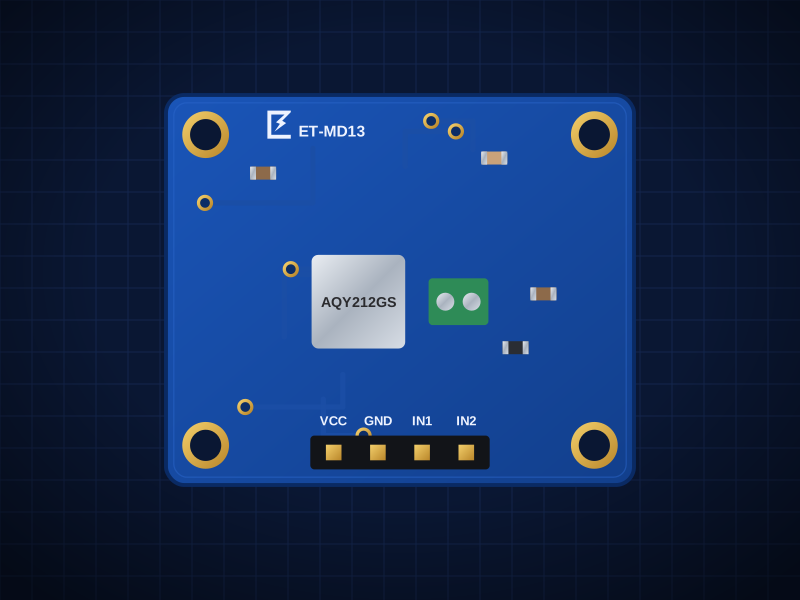
ET-MD13
2-Channel PhotoMOS SSR
Silent solid-state switches, 60 V 1 A AC/DC, logic input
AED 39.00
Out of stockOverview
Silent solid-state switches, 60 V 1 A AC/DC, logic input
The ET-MD13 is built around the 2 × Panasonic AQY212GS PhotoMOS, 1 Form A (normally open), 60V AC/DC, 1A, 0.34Ω.
Designed in Dubai by ElectroTrical — the full schematic, BOM and design notes are published below.
Good for
- Switching low-voltage AC or DC loads silently
- Audio and signal switching
- Isolated contact outputs
Key features
What makes it different
Relays
2 × Panasonic AQY212GS PhotoMOS, 1 Form A (normally open), 60V AC/DC, 1A, 0.34Ω
Control
Logic high on IN (3.3/5V), ~6–11mA per channel
Isolation
1.5kV rms input-output (IC rating); board creepage sized for ≤60V circuits only
Switching
Silent, no contact bounce, turn-on ~1.3ms
Open documentation
Schematic, BOM and layout notes published for every board.
Breadboard friendly
Standard 2.54 mm pitch and M2.5 mounting holes.
Specifications
Technical specifications
| Relays | 2 × Panasonic AQY212GS PhotoMOS, 1 Form A (normally open), 60V AC/DC, 1A, 0.34Ω |
|---|---|
| Control | Logic high on IN (3.3/5V), ~6–11mA per channel |
| Isolation | 1.5kV rms input-output (IC rating); board creepage sized for ≤60V circuits only |
| Switching | Silent, no contact bounce, turn-on ~1.3ms |
| Size | 30.0 × 25.0 mm |
|---|---|
| Mounting | 4 × M2.5 holes, 2.54 mm from each corner |
| Connectors | 4-pin 2.54 mm header · Screw terminal 2P 5.0mm 17A (THT) — Isolated outputs |
| Main IC | AQY212GS (LCSC C719745) |
| Revision | Rev A |
| Libraries | Any GPIO; ESPHome switch: gpio |
|---|
Performance
Capability
Pinout
Pin map and connections
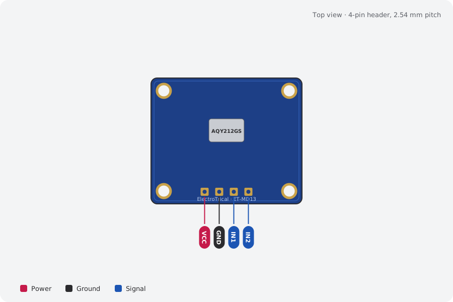
| Pin | Name | Type | Function |
|---|---|---|---|
| 1 | VCC | Power | Spare pin (not connected to the relays) |
| 2 | GND | Ground | Ground |
| 3 | IN1 | Signal | High = channel 1 on |
| 4 | IN2 | Signal | High = channel 2 on |
Mechanical
Dimensions and what's in the box
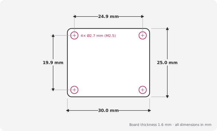
In the box
- 1 × ET-MD13 2-Channel PhotoMOS SSR (assembled)
- 1 × 4-pin 2.54 mm male header, unsoldered
Getting started
- Wire the header: VCC, GND, IN1, IN2
- Libraries: Any GPIO
Compare
Which load switch?
| 2-Channel PhotoMOS SSR (this board)This board | ET-MD14 High-Current MOSFET PWM Switch | ET-MD17 2-Channel High-Side Switch | ET-MD08 4-Channel MOSFET Driver | |
|---|---|---|---|---|
| What it does | Silent solid-state switches, 60 V 1 A AC/DC, logic input | Gate-driven 30 V MOSFET for 10 A loads, fast PWM from 3.3 V | Protected 5–34 V high-side outputs for 12/24 V loads | Four logic-level low-side switches, 3 A each up to 24 V |
| Interface | Logic high on IN (3.3/5V), ~6–11mA per channel | PWM up to 200kHz from 3.3/5V logic | 3.3/5V logic inputs, status (fault) outputs | 3.3V and 5V logic, < 1µA |
| Best for | Switching low-voltage AC or DC loads silently | Heaters and LED strips | Valves and solenoids on 24 V | LED strips and lighting |
| Price | 39 AED | 39 AED | 25 AED | 16 AED |
Downloads
Documents and design files
Need a custom version of this board?
Different connector, size or sensor? We design and build custom variants.