
ET-S26
LSM6DSOX 6-DoF IMU
Accelerometer + gyro with machine-learning core
AED 39.00
Out of stockOverview
Accelerometer + gyro with machine-learning core
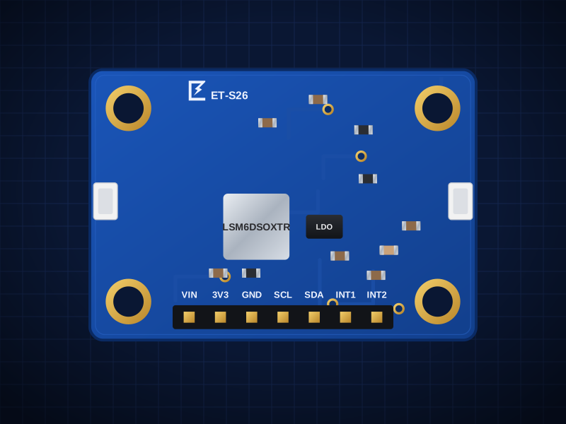
The ET-S26 is built around the ST LSM6DSOX — ±2–16g accel, ±125–2000dps gyro, FSM + Machine-Learning Core, 9kB FIFO. It connects over I²C 0x6A / 0x6B (JP3) (INT1/INT2) and is powered from VIN 3.3–5.5V, onboard LDO.
Two Qwiic / STEMMA QT connectors let you chain it with other boards without soldering, and the 2.54 mm header fits a breadboard.
Designed in Dubai by ElectroTrical — the full schematic, BOM and design notes are published below.
Good for
- Activity and gesture recognition
- Wearables
- Tilt and vibration sensing
Key features
What makes it different
Sensor
ST LSM6DSOX: ±2–16g accel, ±125–2000dps gyro, FSM + Machine-Learning Core, 9kB FIFO
Interface
I2C 0x6A / 0x6B (JP3), INT1/INT2
Supply
VIN 3.3–5.5V, onboard LDO
Libraries
Adafruit_LSM6DS / CircuitPython, ST STM32duino LSM6DSOX, ESPHome (external)
Qwiic / STEMMA QT
Two JST-SH connectors plus a 2.54 mm header — 3.3 V and 5 V hosts.
Open documentation
Schematic, BOM and layout notes published for every board.
Specifications
Technical specifications
| Sensor | ST LSM6DSOX: ±2–16g accel, ±125–2000dps gyro, FSM + Machine-Learning Core, 9kB FIFO |
|---|---|
| Interface | I2C 0x6A / 0x6B (JP3), INT1/INT2 |
| Supply | VIN 3.3–5.5V, onboard LDO |
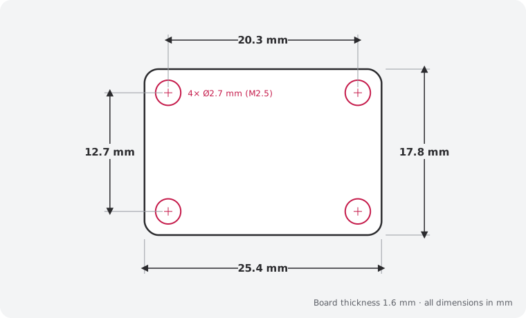
| Size | 25.4 × 17.8 mm |
|---|---|
| Mounting | 4 × M2.5 holes, 2.54 mm from each corner |
| Connectors | 2 × Qwiic / STEMMA QT (JST SH 4-pin) · 7-pin 2.54 mm header |
| Main IC | LSM6DSOXTR (LCSC C481766) |
| Revision | Rev B |
| Libraries | Adafruit_LSM6DS / CircuitPython, ST STM32duino LSM6DSOX, ESPHome (external) |
|---|
| JP1 (default Closed) | Cut to turn off the LED |
|---|---|
| JP2 (default Closed) | Cut to remove the host-side I2C pull-ups |
| JP3 (default Open) | Bridge → SA0=3V3 → address 0x6B |
Performance
Gyroscope ranges
Pinout
Pin map and connections
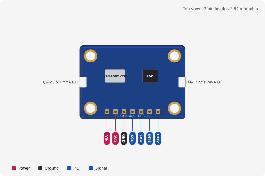
| Pin | Name | Type | Function |
|---|---|---|---|
| 1 | VIN | Power | 3.3–5.5V |
| 2 | 3V3 | Power | LDO output |
| 3 | GND | Ground | Ground |
| 4 | SCL | I²C | I²C clock |
| 5 | SDA | I²C | I²C data |
| 6 | INT1 | Signal | Host level |
| 7 | INT2 | Signal | Host level |
Qwiic / STEMMA QT pins: GND, VIN, SDA, SCL (same on both connectors). I²C pull-ups (10 kΩ) are on the board; cut JP2 to remove them.
Mechanical
Dimensions and what's in the box
In the box
- 1 × ET-S26 LSM6DSOX 6-DoF IMU (assembled)
- 1 × 7-pin 2.54 mm male header, unsoldered
Getting started
- Plug in a Qwiic / STEMMA QT cable, or solder the header and wire VIN, GND, SDA and SCL
- Libraries: Adafruit_LSM6DS / CircuitPython, ST STM32duino LSM6DSOX, ESPHome (external)
- Run an I²C scanner to confirm the address: 0x6A, 0x6B
Compare
Which motion sensor?
| LSM6DSOX 6-DoF IMU (this board)This board | ET-S04 BNO085 9-DoF Orientation IMU | ET-S27 ICM-42688-P Low-Noise IMU | ET-S29 ADXL345 ±16 g Accelerometer | |
|---|---|---|---|---|
| What it does | Accelerometer + gyro with machine-learning core | On-chip sensor fusion: quaternions, heading, steps | Flight-controller grade 6-DoF IMU | 3-axis digital accelerometer, I²C/SPI |
| Interface | I²C 0x6A / 0x6B (JP3), INT1/INT2 | I²C 0x4A (default) / 0x4B (JP3); UART-RVC mode… | I²C 0x68/0x69 through shifters (Qwiic) or direct… | I²C 0x53 (default) / 0x1D, INT1/INT2 |
| Best for | Activity and gesture recognition | Robot and drone orientation | Drone and FPV flight controllers | Tilt and tap detection |
| Price | 39 AED | 79 AED | 49 AED | 59 AED |
Downloads
Documents and design files
Need a custom version of this board?
Different connector, size or sensor? We design and build custom variants.