
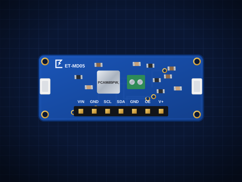
ET-MD05
PCA9685 16-Channel Servo Driver
16 servos or PWM LEDs from two I²C pins, Qwiic
AED 49.00
Out of stockOverview
16 servos or PWM LEDs from two I²C pins, Qwiic
The ET-MD05 is built around the NXP PCA9685 — 16 independent 12-bit PWM outputs, 24Hz–1526Hz, internal 25MHz oscillator. It connects over I²C up to 1MHz (address 0x40 (6 jumpers → 62 boards on one bus); Qwiic / STEMMA QT) and is powered from Logic 2.3–5.5V; servo power V+ 4.8–6V on the terminal, up to ~8A total through the board.
Two Qwiic / STEMMA QT connectors let you chain it with other boards without soldering, and the 2.54 mm header fits a breadboard.
Designed in Dubai by ElectroTrical — the full schematic, BOM and design notes are published below.
Good for
- Robot arms and hexapods
- Animatronics
- Dimming many LED channels
Key features
What makes it different
Controller
NXP PCA9685: 16 independent 12-bit PWM outputs, 24Hz–1526Hz, internal 25MHz oscillator
Interface
I²C up to 1MHz, address 0x40 (6 jumpers → 62 boards on one bus); Qwiic / STEMMA QT
Supply
Logic 2.3–5.5V; servo power V+ 4.8–6V on the terminal, up to ~8A total through the board
Outputs
16 × 3-pin servo headers, 220Ω series resistors (LEDs can be driven directly, 25mA sink)
Qwiic / STEMMA QT
Two JST-SH connectors plus a 2.54 mm header — 3.3 V and 5 V hosts.
Open documentation
Schematic, BOM and layout notes published for every board.
Specifications
Technical specifications
| Controller | NXP PCA9685: 16 independent 12-bit PWM outputs, 24Hz–1526Hz, internal 25MHz oscillator |
|---|---|
| Interface | I²C up to 1MHz, address 0x40 (6 jumpers → 62 boards on one bus); Qwiic / STEMMA QT |
| Supply | Logic 2.3–5.5V; servo power V+ 4.8–6V on the terminal, up to ~8A total through the board |
| Outputs | 16 × 3-pin servo headers, 220Ω series resistors (LEDs can be driven directly, 25mA sink) |
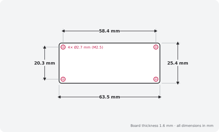
| Size | 63.5 × 25.4 mm |
|---|---|
| Mounting | 4 × M2.5 holes, 2.54 mm from each corner |
| Connectors | 2 × Qwiic / STEMMA QT (JST SH 4-pin) · 7-pin 2.54 mm header · Screw terminal 2P 5.0mm 17A (THT) — Servo power V+ (5–6V) |
| Main IC | PCA9685PW,118 (LCSC C2678753) |
| Revision | Rev A |
| Libraries | Adafruit_PWMServoDriver (Arduino), adafruit-circuitpython-pca9685 / servokit |
|---|
| JP1 (default Closed) | Power LED (cut = off) |
|---|---|
| JP2 (default Closed) | I²C pull-ups |
| JP3–JP8 (default Open) | Bridge to set A0–A5 → address 0x40–0x7F |
Performance
PWM frequency
Pinout
Pin map and connections
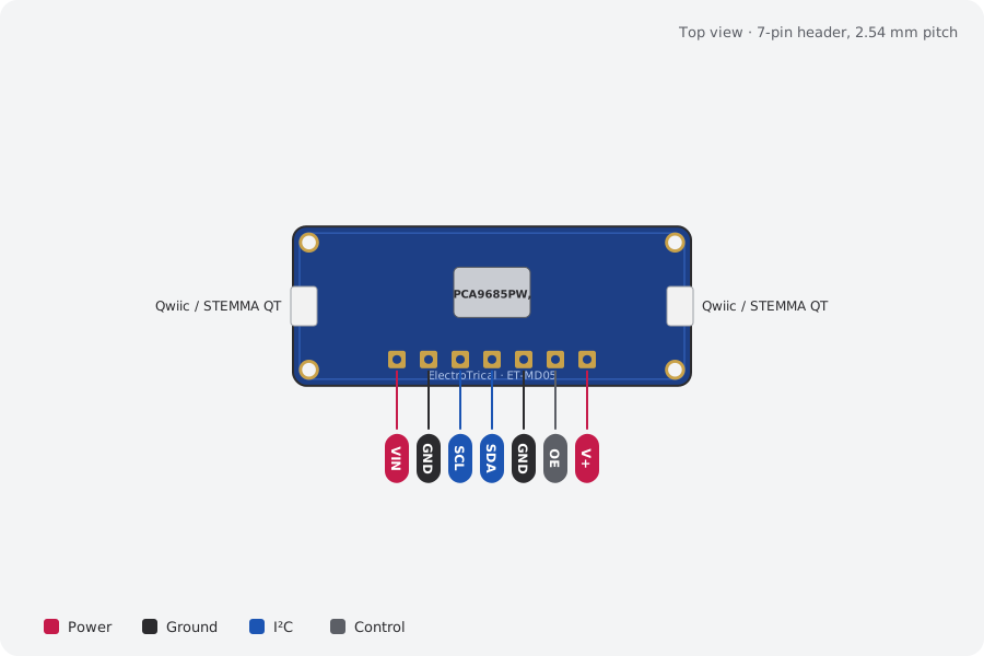
| Pin | Name | Type | Function |
|---|---|---|---|
| 1 | VIN | Power | Logic 2.3–5.5V |
| 2 | GND | Ground | Ground |
| 3 | SCL | I²C | I²C clock |
| 4 | SDA | I²C | I²C data |
| 5 | GND | Ground | Ground |
| 6 | OE | Control | High = all outputs off |
| 7 | V+ | Power | Servo power (same as J4) |
Qwiic / STEMMA QT pins: GND, VIN, SDA, SCL (same on both connectors). I²C pull-ups (10 kΩ) are on the board; cut JP2 to remove them.
Mechanical
Dimensions and what's in the box
In the box
- 1 × ET-MD05 PCA9685 16-Channel Servo Driver (assembled)
- 1 × 7-pin 2.54 mm male header, unsoldered
- 1 × 2.54mm 3x16 male header (servo, ship loose)
Getting started
- Plug in a Qwiic / STEMMA QT cable, or solder the header and wire VIN, GND, SDA and SCL
- Libraries: Adafruit_PWMServoDriver (Arduino), adafruit-circuitpython-pca9685 / servokit
- Run an I²C scanner to confirm the address: 0x40
Compare
Which output driver?
| PCA9685 16-Channel Servo Driver (this board)This board | ET-MD07 2-Channel 5 V Relay Board | ET-MD08 4-Channel MOSFET Driver | ET-MD10 ULN2803 8-Channel Sink Driver | |
|---|---|---|---|---|
| What it does | 16 servos or PWM LEDs from two I²C pins, Qwiic | Two SPDT relays with active-high 3.3 V / 5 V inputs | Four logic-level low-side switches, 3 A each up to 24 V | Eight 500 mA Darlington outputs with flyback diodes |
| Interface | I²C up to 1MHz, address 0x40 (6 jumpers → 62… | Active-high, 3.3V and 5V logic, ~2.6mA per input;… | 3.3V and 5V logic, < 1µA | 5V TTL / CMOS; 3.3V logic works for lighter loads… |
| Best for | Robot arms and hexapods | Switching low-voltage pumps, valves and lamps | LED strips and lighting | 28BYJ-48 unipolar steppers |
| Price | 49 AED | 12 AED | 16 AED | 12 AED |
Downloads
Documents and design files
Need a custom version of this board?
Different connector, size or sensor? We design and build custom variants.