
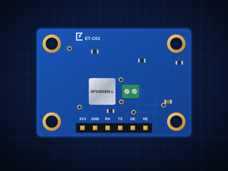
ET-C01
RS-485 Transceiver
Half-duplex RS-485 for Modbus and long UART runs, 3.3 V
AED 9.00
Out of stockOverview
Half-duplex RS-485 for Modbus and long UART runs, 3.3 V
The ET-C01 is built around the MaxLinear SP3485 — half-duplex RS-485/RS-422, 10Mbps, 1/8 unit load (up to 32 nodes). It talks over UART RX/TX + DE/RE direction pins, 3.3V logic.
Designed in Dubai by ElectroTrical — the full schematic, BOM and design notes are published below.
Good for
- Modbus RTU sensors and meters
- DMX lighting
- UART over hundreds of metres
Key features
What makes it different
Transceiver
MaxLinear SP3485: half-duplex RS-485/RS-422, 10Mbps, 1/8 unit load (up to 32 nodes)
Interface
UART RX/TX + DE/RE direction pins, 3.3V logic
Bus
Screw terminal A / B / GND, optional 120Ω termination
Use
Modbus RTU, DMX512, long-distance UART (up to 1200m)
Open documentation
Schematic, BOM and layout notes published for every board.
Breadboard friendly
Standard 2.54 mm pitch and M2.5 mounting holes.
Specifications
Technical specifications
| Transceiver | MaxLinear SP3485: half-duplex RS-485/RS-422, 10Mbps, 1/8 unit load (up to 32 nodes) |
|---|---|
| Interface | UART RX/TX + DE/RE direction pins, 3.3V logic |
| Bus | Screw terminal A / B / GND, optional 120Ω termination |
| Use | Modbus RTU, DMX512, long-distance UART (up to 1200m) |
| Size | 25.4 × 17.8 mm |
|---|---|
| Mounting | 4 × M2.5 holes, 2.54 mm from each corner |
| Connectors | 6-pin 2.54 mm header |
| Main IC | SP3485EN-L/TR (LCSC C8963) |
| Revision | Rev A |
| JP1 (default Open) | Bridge DE + RE# → one direction pin |
|---|---|
| JP2 (default Open) | Bridge to add 120Ω termination (end-of-line node only) |
Performance
Cable length
Pinout
Pin map and connections
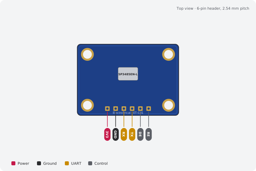
| Pin | Name | Type | Function |
|---|---|---|---|
| 1 | 3V3 | Power | 3.0–3.6V |
| 2 | GND | Ground | Ground |
| 3 | RX | UART | Receiver out (RO) → host RX |
| 4 | TX | UART | Host TX → driver in (DI) |
| 5 | DE | Control | High = transmit |
| 6 | RE | Control | Low = receive (RE#) |
I²C pull-ups (10 kΩ) are on the board; cut JP2 to remove them.
Mechanical
Dimensions and what's in the box
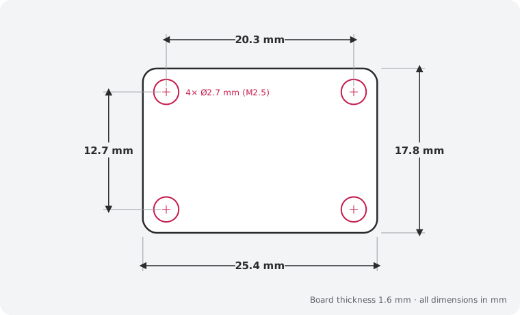
In the box
- 1 × ET-C01 RS-485 Transceiver (assembled)
- 1 × 6-pin 2.54 mm male header, unsoldered
Getting started
- Wire the header: 3V3, GND, RX, TX, DE, RE
Compare
Which industrial bus board?
| RS-485 Transceiver (this board)This board | ET-C10 USB-C to RS-485 Adapter | ET-C02 CAN Bus Transceiver | ET-C09 MCP2515 SPI CAN Board | |
|---|---|---|---|---|
| What it does | Half-duplex RS-485 for Modbus and long UART runs, 3.3 V | Modbus RTU from your PC over USB-C | 3.3 V CAN transceiver for MCUs with built-in CAN | CAN controller + 3.3 V transceiver over SPI |
| Interface | UART RX/TX + DE/RE direction pins, 3.3V logic | — | — | — |
| Best for | Modbus RTU sensors and meters | Modbus RTU from a laptop | ESP32 TWAI and STM32 CAN projects | CAN on Raspberry Pi and Arduino |
| Price | 9 AED | 28 AED | 12 AED | 9 AED |
Downloads
Documents and design files
Need a custom version of this board?
Different connector, size or sensor? We design and build custom variants.