
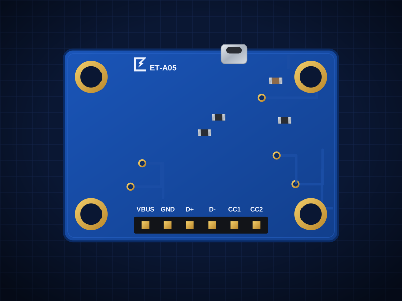
ET-A05
USB-C Breakout
USB-C power and USB 2.0 data on a 0.1" header
AED 9.00
Out of stock✓ TestedEvery board is checked before it ships
🚚 Fast shippingUAE 1–3 days · GCC & worldwide
💬 Engineer supportQuestions answered by the designers
Overview
USB-C power and USB 2.0 data on a 0.1" header
The ET-A05 is built around the USB-C receptacle, USB 2.0 (D+/D− on both orientations), mid-mount 16-pin.
Designed in Dubai by ElectroTrical — the full schematic, BOM and design notes are published below.
Good for
- Adding USB-C power to a project
- Breadboard USB experiments
- Replacing old micro-USB inputs
Key features
What makes it different
Connector
USB-C receptacle, USB 2.0 (D+/D− on both orientations), mid-mount 16-pin
Power
5.1k Rd on CC1/CC2 → any USB-C charger or port supplies 5V (up to 3A depending on the source)
Signals
VBUS, GND, D+, D−, CC1, CC2 on a 2.54mm header
Open documentation
Schematic, BOM and layout notes published for every board.
Breadboard friendly
Standard 2.54 mm pitch and M2.5 mounting holes.
Specifications
Technical specifications
| Connector | USB-C receptacle, USB 2.0 (D+/D− on both orientations), mid-mount 16-pin |
|---|---|
| Power | 5.1k Rd on CC1/CC2 → any USB-C charger or port supplies 5V (up to 3A depending on the source) |
| Signals | VBUS, GND, D+, D−, CC1, CC2 on a 2.54mm header |
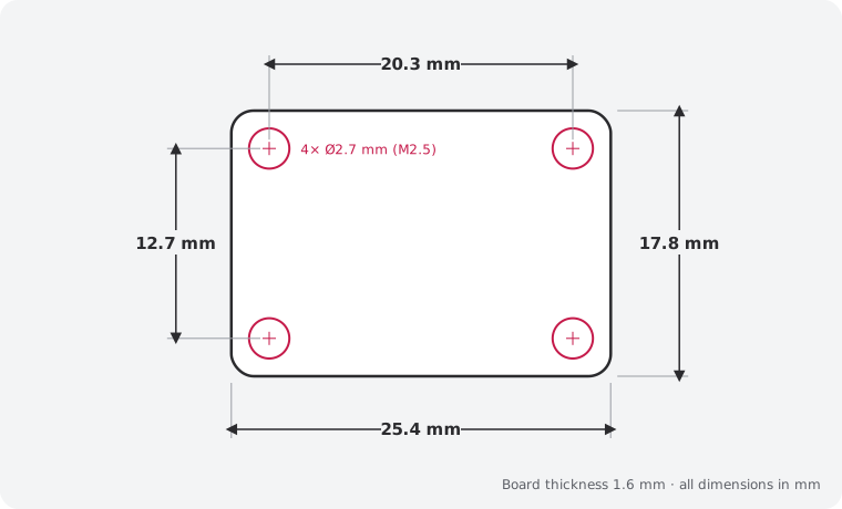
| Size | 25.4 × 17.8 mm |
|---|---|
| Mounting | 4 × M2.5 holes, 2.54 mm from each corner |
| Connectors | 6-pin 2.54 mm header · USB-C 16P receptacle (USB 2.0) — USB-C receptacle (16P, USB 2.0) |
| Revision | Rev A |
| JP1, JP2 (default Closed) | Cut both to remove the 5.1k Rd (custom CC / PD use) |
|---|
Performance
Power
Pinout
Pin map and connections
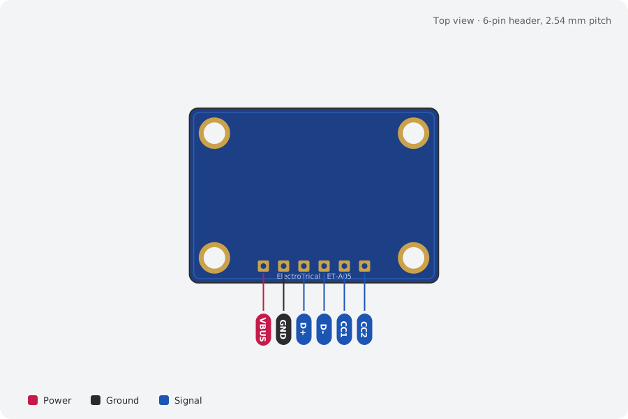
| Pin | Name | Type | Function |
|---|---|---|---|
| 1 | VBUS | Power | 5V from the source |
| 2 | GND | Ground | Ground |
| 3 | D+ | Signal | USB data + |
| 4 | D- | Signal | USB data − |
| 5 | CC1 | Signal | CC1 |
| 6 | CC2 | Signal | CC2 |
Mechanical
Dimensions and what's in the box
In the box
- 1 × ET-A05 USB-C Breakout (assembled)
- 1 × 6-pin 2.54 mm male header, unsoldered
Getting started
- Wire the header: VBUS, GND, D+, D-, CC1, CC2
Compare
Which USB / power helper?
| USB-C Breakout (this board)This board | ET-A06 USB-C Breadboard Power Supply | ET-A09 5V Arduino to Qwiic Adapter | |
|---|---|---|---|
| What it does | USB-C power and USB 2.0 data on a 0.1" header | 5 V and 3.3 V on both breadboard rails from USB-C | Safe 3.3 V power and I²C levels for Qwiic on 5 V boards |
| Interface | — | USB-C 5V (Rd on CC → works with any USB-C… | — |
| Best for | Adding USB-C power to a project | Breadboard prototyping | Qwiic sensors on Arduino Uno and Mega |
| Price | 9 AED | 9 AED | 23 AED |
Downloads
Documents and design files
PDFET-A05 schematicRev A
STEP3D modelComing soon
Need a custom version of this board?
Different connector, size or sensor? We design and build custom variants.