
ET-S07
INA228 85 V Power Monitor
20-bit current, voltage, power and energy monitor
AED 59.00
Out of stockOverview
20-bit current, voltage, power and energy monitor
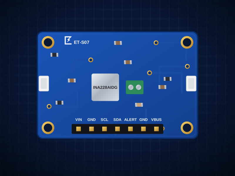
The ET-S07 is built around the TI INA228 — 20-bit ΔΣ, 0–85V common mode, current/bus V/power/energy/charge/die temperature. It connects over I²C 0x40 default; 0x41/0x44/0x45 via JP3/JP4 (16 possible in total) and is powered from VIN 2.7–5.5V (no LDO needed; I2C follows VIN).
Two Qwiic / STEMMA QT connectors let you chain it with other boards without soldering, and the 2.54 mm header fits a breadboard.
Designed in Dubai by ElectroTrical — the full schematic, BOM and design notes are published below.
Good for
- Battery and solar monitoring
- Motor and drone power logging
- Bench power measurement
Key features
What makes it different
IC
TI INA228: 20-bit ΔΣ, 0–85V common mode, current/bus V/power/energy/charge/die temperature
Range
±10.9A with the 15mΩ shunt (±163.84mV range), resolution ≈ 20µA
Interface
I2C 0x40 default; 0x41/0x44/0x45 via JP3/JP4 (16 possible in total)
Supply
VIN 2.7–5.5V (no LDO needed; I2C follows VIN)
Qwiic / STEMMA QT
Two JST-SH connectors plus a 2.54 mm header — 3.3 V and 5 V hosts.
Open documentation
Schematic, BOM and layout notes published for every board.
Specifications
Technical specifications
| IC | TI INA228: 20-bit ΔΣ, 0–85V common mode, current/bus V/power/energy/charge/die temperature |
|---|---|
| Range | ±10.9A with the 15mΩ shunt (±163.84mV range), resolution ≈ 20µA |
| Interface | I2C 0x40 default; 0x41/0x44/0x45 via JP3/JP4 (16 possible in total) |
| Supply | VIN 2.7–5.5V (no LDO needed; I2C follows VIN) |
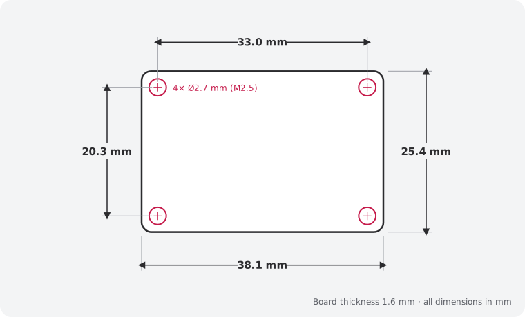
| Size | 38.1 × 25.4 mm |
|---|---|
| Mounting | 4 × M2.5 holes, 2.54 mm from each corner |
| Connectors | 2 × Qwiic / STEMMA QT (JST SH 4-pin) · 7-pin 2.54 mm header · Screw terminal 2P 5.0mm 17A (THT) — Power terminal SOURCE+/LOAD+ (THT; JLCPCB THT assembly or hand-solder) |
| Main IC | INA228AIDGSR (LCSC C2887910) |
| Revision | Rev B |
| Libraries | Adafruit_INA228 / CircuitPython, RobTillaart INA228, ESPHome ina2xx_i2c |
|---|
| JP1 (default Closed) | Cut to turn off the LED |
|---|---|
| JP2 (default Closed) | Cut to remove the I2C pull-ups |
| JP3 (default A–C (GND)) | A0: cut and bridge B–C → VS |
| JP4 (default A–C (GND)) | A1: cut and bridge B–C → VS |
Performance
Measurement range
Pinout
Pin map and connections
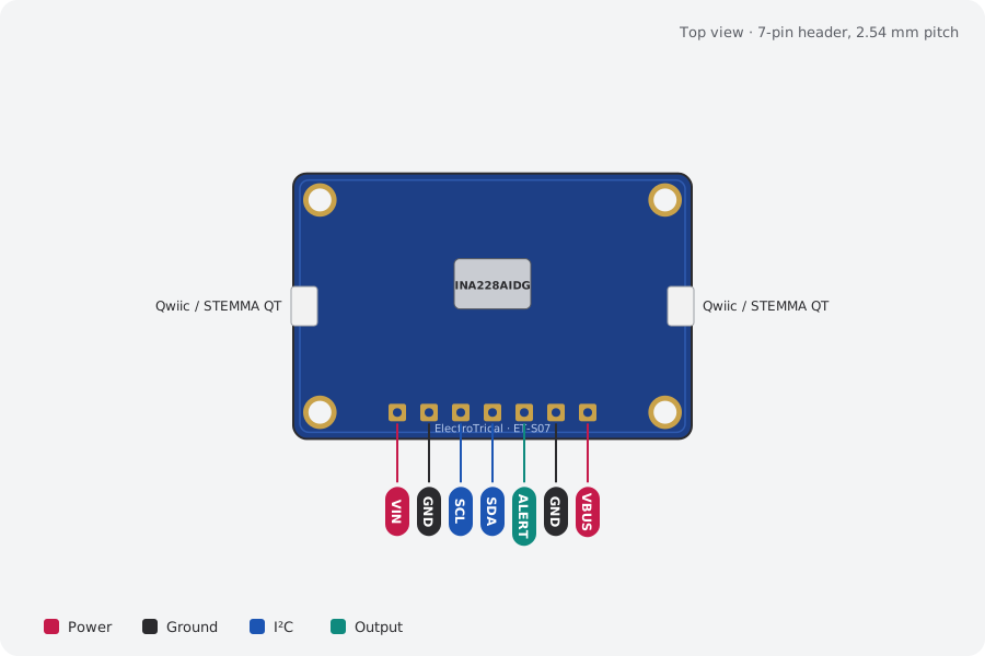
| Pin | Name | Type | Function |
|---|---|---|---|
| 1 | VIN | Power | 2.7–5.5V |
| 2 | GND | Ground | Must be shared with the measured circuit's negative |
| 3 | SCL | I²C | I²C clock |
| 4 | SDA | I²C | I²C data |
| 5 | ALERT | Output | Open-drain, active low |
| 6 | GND | Ground | Ground |
| 7 | VBUS | Power | Bus-voltage input (internally linked to LOAD+ through R6) |
Qwiic / STEMMA QT pins: GND, VIN, SDA, SCL (same on both connectors). I²C pull-ups (10 kΩ) are on the board; cut JP2 to remove them.
Mechanical
Dimensions and what's in the box
In the box
- 1 × ET-S07 INA228 85 V Power Monitor (assembled)
- 1 × 7-pin 2.54 mm male header, unsoldered
Getting started
- Plug in a Qwiic / STEMMA QT cable, or solder the header and wire VIN, GND, SDA and SCL
- Libraries: Adafruit_INA228 / CircuitPython, RobTillaart INA228, ESPHome
ina2xx_i2c - Run an I²C scanner to confirm the address: 0x40, 0x41, 0x44
Compare
Which current and power board?
| INA228 85 V Power Monitor (this board)This board | ET-S37 ACS725 ±20 A Current Sensor | ET-S38 2-Channel CT Clamp Interface | ET-S39 ATM90E32 3-Phase Energy Monitor | |
|---|---|---|---|---|
| What it does | 20-bit current, voltage, power and energy monitor | Isolated Hall current sensor with 16-bit I²C ADC | SCT-013 clamp interface with 16-bit I²C ADC | 3-phase energy metering IC with CT inputs |
| Interface | I²C 0x40 default; 0x41/0x44/0x45 via JP3/JP4 (16… | I²C 0x48; raw analog VIOUT also on J3.6 | I²C 0x48 | SPI (mode 3) on J3. No Qwiic (SPI part) |
| Best for | Battery and solar monitoring | Motor current monitoring | Home energy monitoring | 3-phase energy metering |
| Price | 59 AED | 49 AED | 49 AED | 219 AED |
Downloads
Documents and design files
Need a custom version of this board?
Different connector, size or sensor? We design and build custom variants.