
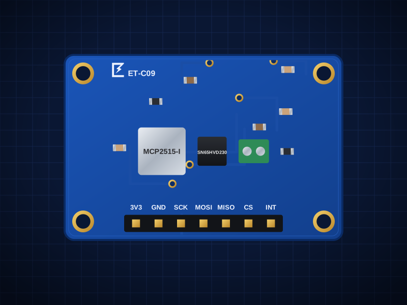
ET-C09
MCP2515 SPI CAN Board
CAN controller + 3.3 V transceiver over SPI
AED 9.00
Out of stockOverview
CAN controller + 3.3 V transceiver over SPI
The ET-C09 is built around the Microchip MCP2515 — CAN 2.0B up to 1Mbps, 3 TX + 2 RX buffers, 6 filters.
Designed in Dubai by ElectroTrical — the full schematic, BOM and design notes are published below.
Good for
- CAN on Raspberry Pi and Arduino
- Car OBD-II experiments
- Robot and e-bike buses
Key features
What makes it different
Controller
Microchip MCP2515: CAN 2.0B up to 1Mbps, 3 TX + 2 RX buffers, 6 filters
Transceiver
TI SN65HVD230, 3.3V — runs from 3.3V boards (ESP32, Pi, RP2040) without level shifting
Clock
8MHz crystal (set 8MHz in the library)
Libraries
autowp mcp2515, Sandeep CAN (Arduino), Linux mcp251x overlay on Raspberry Pi
Open documentation
Schematic, BOM and layout notes published for every board.
Breadboard friendly
Standard 2.54 mm pitch and M2.5 mounting holes.
Specifications
Technical specifications
| Controller | Microchip MCP2515: CAN 2.0B up to 1Mbps, 3 TX + 2 RX buffers, 6 filters |
|---|---|
| Transceiver | TI SN65HVD230, 3.3V — runs from 3.3V boards (ESP32, Pi, RP2040) without level shifting |
| Clock | 8MHz crystal (set 8MHz in the library) |
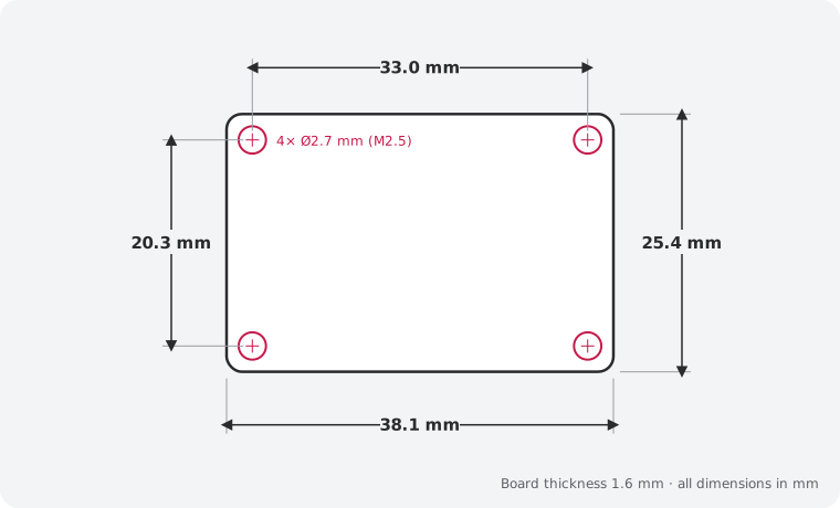
| Size | 38.1 × 25.4 mm |
|---|---|
| Mounting | 4 × M2.5 holes, 2.54 mm from each corner |
| Connectors | 7-pin 2.54 mm header |
| Main IC | MCP2515-I/SO (LCSC C12368) |
| Revision | Rev A |
| Libraries | autowp mcp2515, Sandeep CAN (Arduino), Linux mcp251x overlay on Raspberry Pi |
|---|
| JP1 (default Open) | Bridge to add 120Ω termination |
|---|
Performance
Bus length
Pinout
Pin map and connections
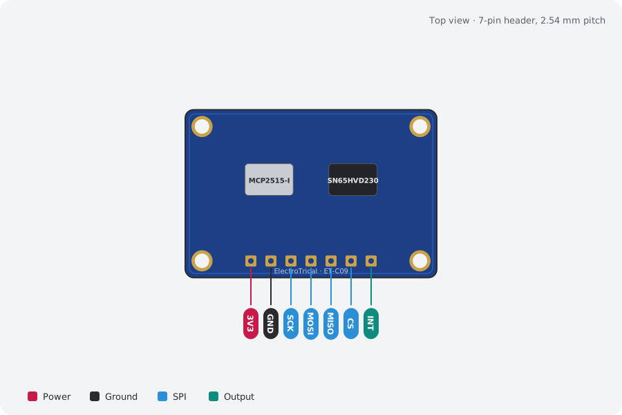
| Pin | Name | Type | Function |
|---|---|---|---|
| 1 | 3V3 | Power | 3.0–3.6V |
| 2 | GND | Ground | Ground |
| 3 | SCK | SPI | SPI clock ≤10MHz |
| 4 | MOSI | SPI | MOSI |
| 5 | MISO | SPI | MISO |
| 6 | CS | SPI | Active low |
| 7 | INT | Output | Active low |
Mechanical
Dimensions and what's in the box
In the box
- 1 × ET-C09 MCP2515 SPI CAN Board (assembled)
- 1 × 7-pin 2.54 mm male header, unsoldered
Getting started
- Wire the header: 3V3, GND, SCK, MOSI, MISO, CS
- Libraries: autowp mcp2515, Sandeep CAN (Arduino), Linux mcp251x overlay on Raspberry Pi
Compare
Which industrial bus board?
| MCP2515 SPI CAN Board (this board)This board | ET-C01 RS-485 Transceiver | ET-C10 USB-C to RS-485 Adapter | ET-C02 CAN Bus Transceiver | |
|---|---|---|---|---|
| What it does | CAN controller + 3.3 V transceiver over SPI | Half-duplex RS-485 for Modbus and long UART runs, 3.3 V | Modbus RTU from your PC over USB-C | 3.3 V CAN transceiver for MCUs with built-in CAN |
| Interface | — | UART RX/TX + DE/RE direction pins, 3.3V logic | — | — |
| Best for | CAN on Raspberry Pi and Arduino | Modbus RTU sensors and meters | Modbus RTU from a laptop | ESP32 TWAI and STM32 CAN projects |
| Price | 9 AED | 9 AED | 28 AED | 12 AED |
Downloads
Documents and design files
Need a custom version of this board?
Different connector, size or sensor? We design and build custom variants.